I’ve recently been making my life more ergonomic and part of this effort is getting a better keyboard. My coworker has been using a Kinesis Advantage since college and after telling him about my efforts to be more ergonomic he showed up the next week with a couple of ancient Kinesis Contoured keyboards (the predecessor to the Kinesis Advantage).
You can check out the repository here
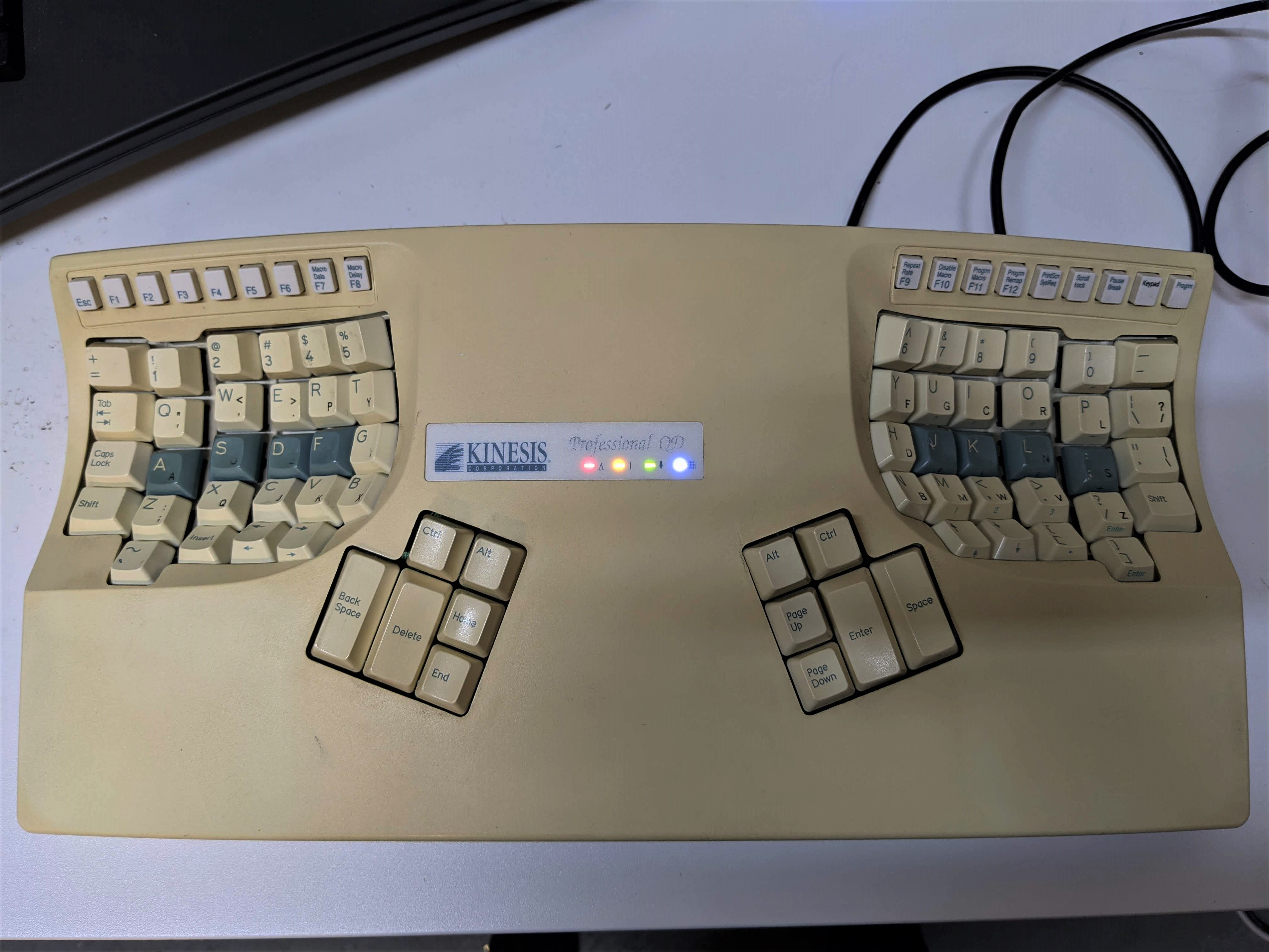
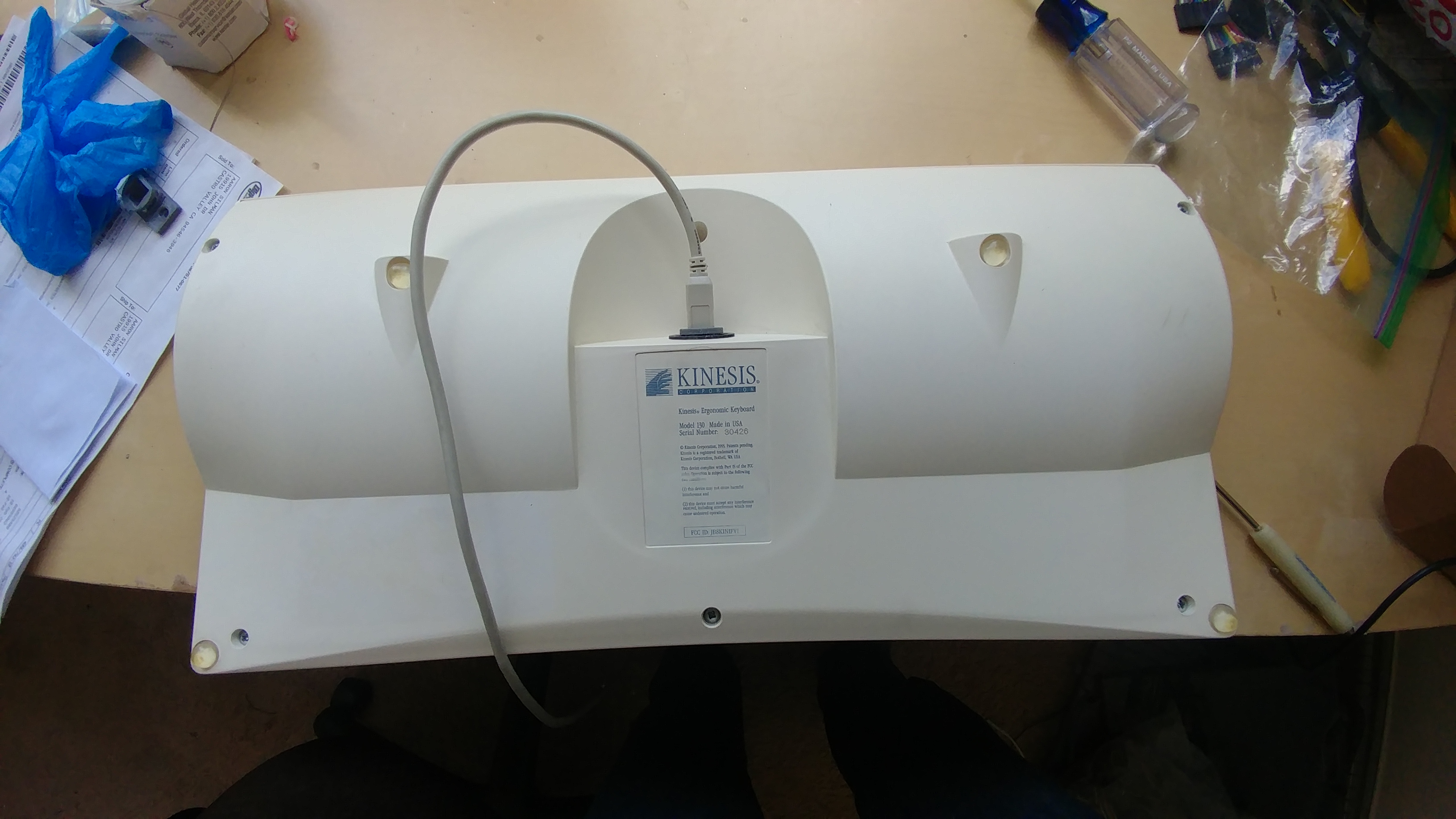
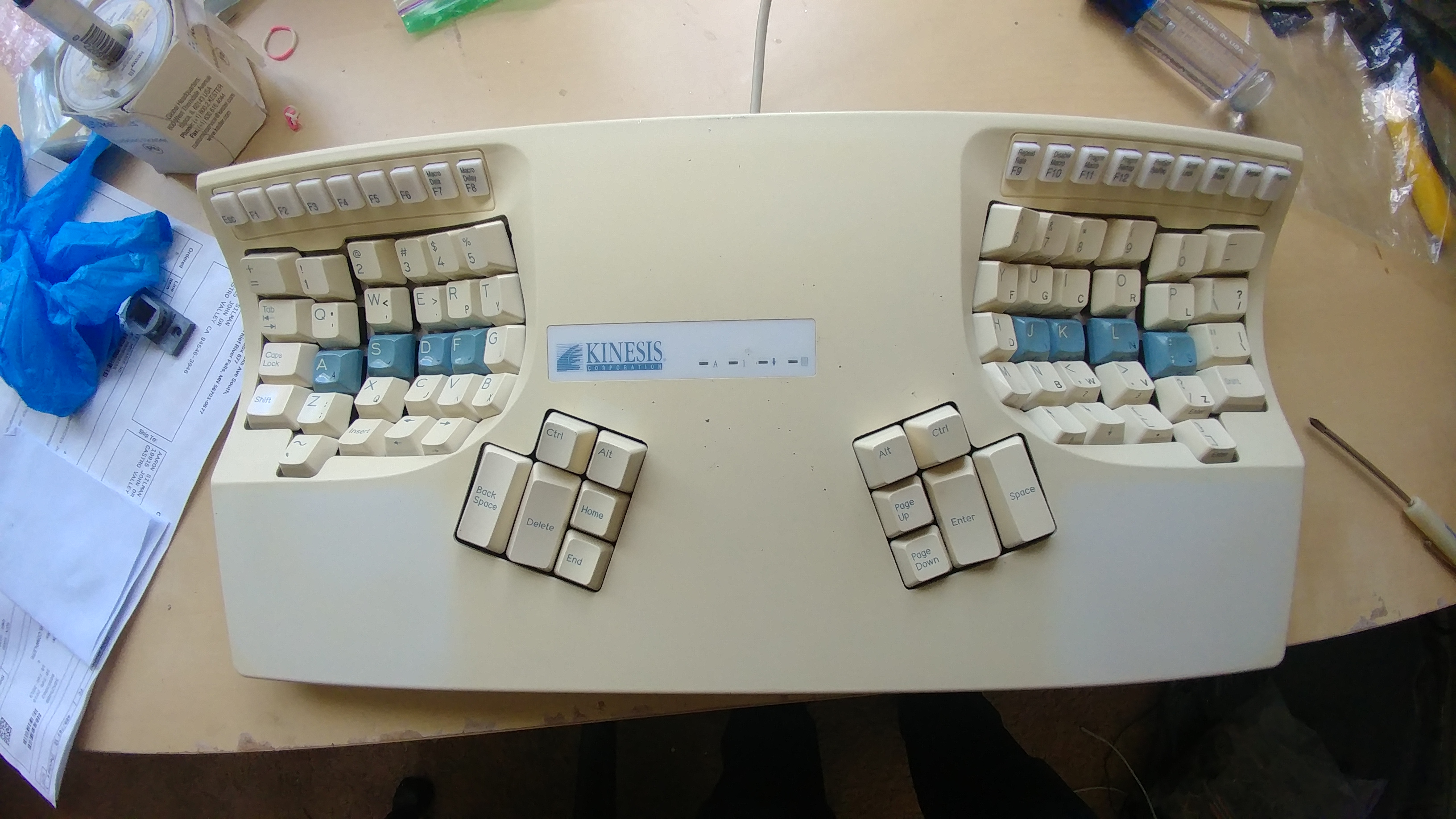
The Kinesis Contoured 130
Both of the keyboard seemed to be from 1995, nearly as old as I am.
One of the keyboard was a Kinesis Contoured 130 Professional QD (which had dual QWERTY and Dvorak legends on the keys) which sported a PS/2 connector connected to a PS/2-to-USB adapter.
The other was a Kinesis Advantage 130 Essential (which did not default come with dual legend keys but I guess the user replaced the keycaps at some point because this one also had dual legend keys). The connector on this one was (I kid you not), a Serial AT connector connected to a Serial AT-to-PS/2 adapter connected to a PS/2-to-USB adapter… it was a monster.
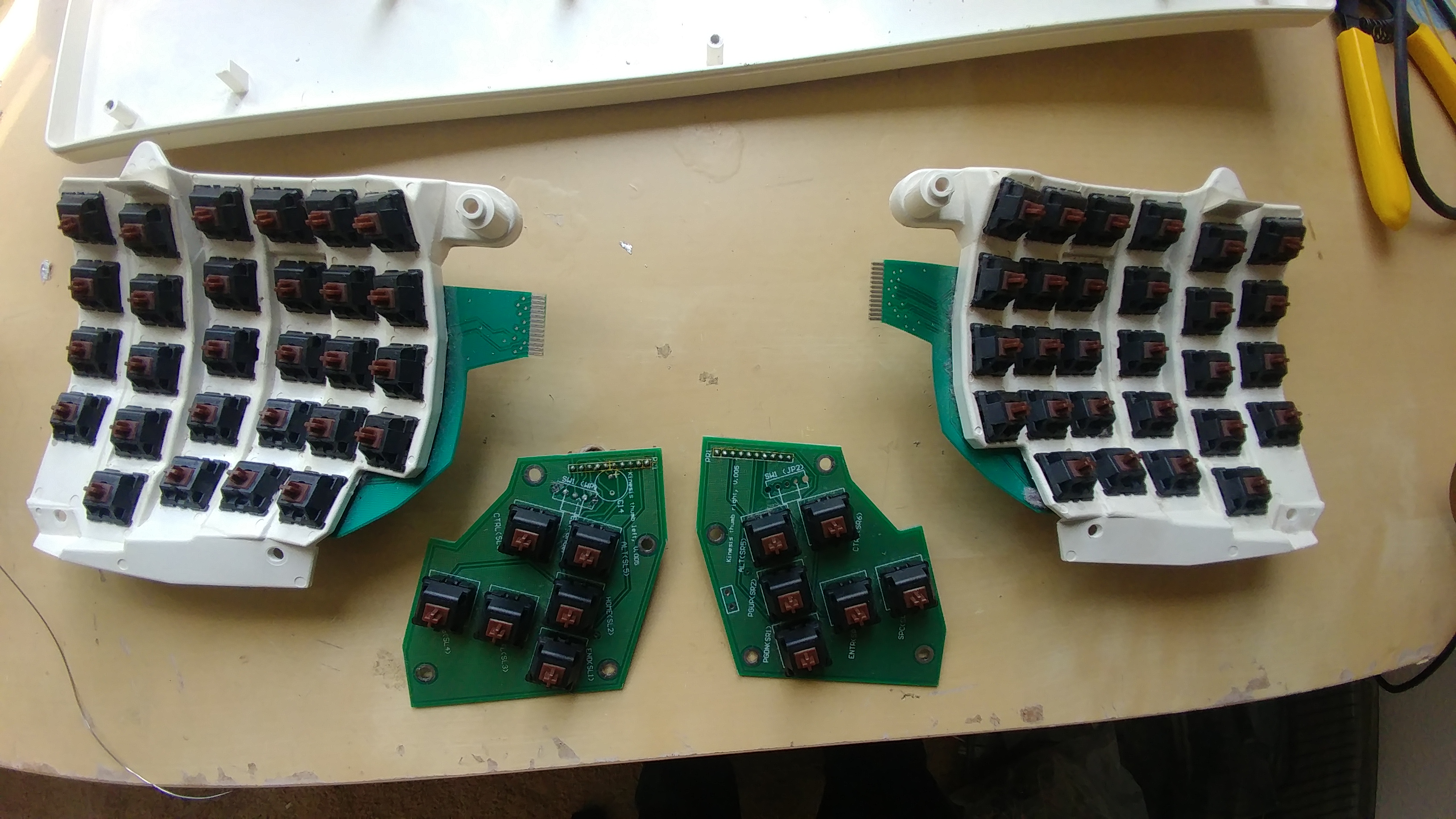
I started by pluggin them both into my spare computer which doesn’t store any personal information (standard opsec when finding USB devices) and checking they work. They did indeed work - albeit with some keys repeating letters. Next I took all the keycaps off and disassembled the keyboard so I could fully clean out the keys with isopropanol. I decided to focus entirely on one keyboard for now.

I knew if I wanted to seriously use these that I had to get them direct to USB so I began looking for some info on who else has dealt with these keyboards.
Stapelberg Mod
The “Stapelberg Mod” is the most common modification that people make to these Kinesis keyboards, you can find details about it here. This information was extremely valuable as he even was tracing the matrix for the Contoured Professional QD (like one of the two I had), so I was confident the matrix would be the same.
The only problem is that the mod was designed for the Kinesis Advantage which has has ribbon cables from the two key wells to the main logic board in the center. These older Kinesis Contoured keyboards had very thin 0.3mm PCB flaps with gold teeth that plugged into a flat-flex connector. In addition to this, the design files for the board was in Eagle CAD (and in German) and I prefered to have them in KiCAD (and in English) in case I wanted to modify anything else. So I got to work porting the design files
Mapping to KiCAD
The Key Matrix
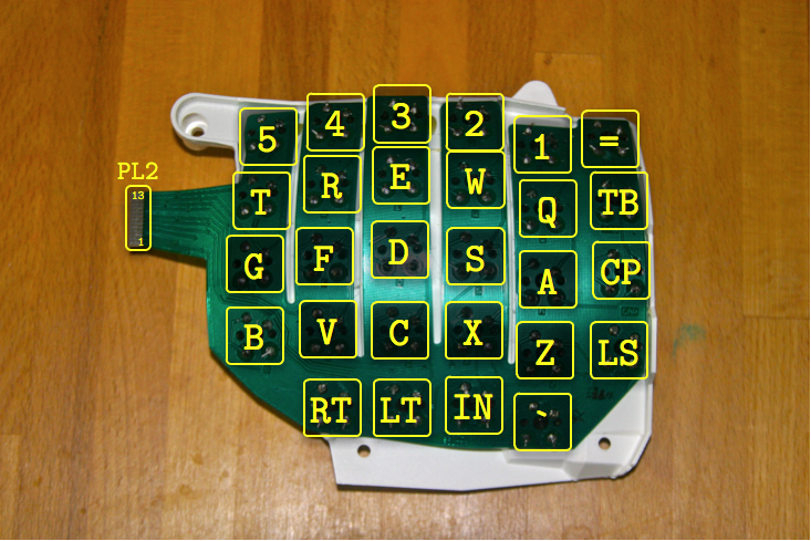
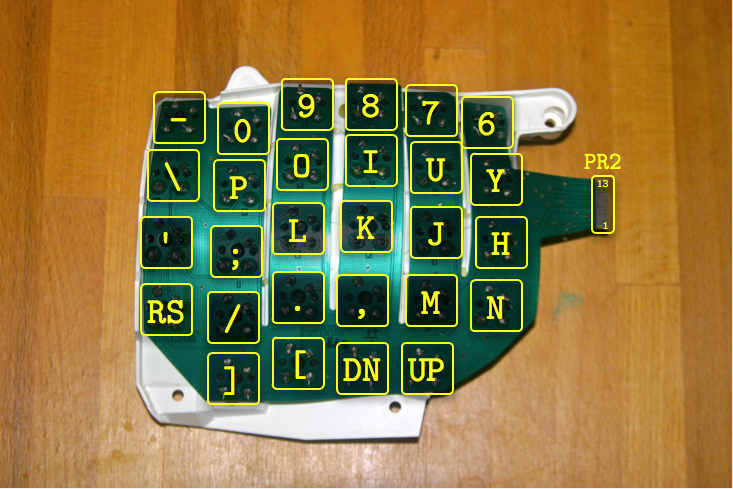
Most of the hard work for this had been taken care of for me by a fellow who mapped all the traces in the key matrix, I just had to follow his guide.
I have reposted his findings here:
Left Hand Key Well
PL2/J2 Connector
| Pin | 6 | 7 | 8 | 10 | 11 | 12 |
|---|---|---|---|---|---|---|
| 1 | \ | IN | LT | RT | ||
| 2 | LS | Z | X | C | V | B |
| 3 | CP | A | S | D | F | G |
| 5 | TB | Q | W | E | R | T |
| 13 | = | 1 | 2 | 3 | 4 | 5 |
Right Hand Key Well
PR1/J1 Connector
| Pin | 1 | 2 | 3 | 6 | 12 | 13 |
|---|---|---|---|---|---|---|
| 4 | UP | DN | [ | ] | ||
| 7 | NS | , | M | RS | . | / |
| 8 | H | K | J | ' | L | ; |
| 9 | Y | I | U | \ | O | P |
| 10 | 6 | 8 | 7 | - | 9 | 0 |
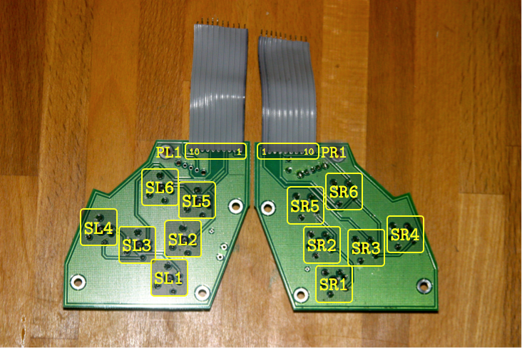
Left Theumb Cluster
PL1/J5 Connector
| Pin | 1 | 2 | 3 | 8 |
|---|---|---|---|---|
| 4 | SL3 | SL6 | SL4 | |
| 5 | SL1 | SL5 | SL2 |
Right Thumb Cluster
PR1/J6 Connector
| Pin | 3 | 4 | 5 | 6 |
|---|---|---|---|---|
| 7 | SR1 | SR2 | SR5 | |
| 8 | SR4 | SR3 | SR6 |
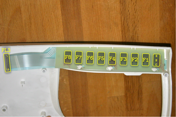
Left Function Keys
PL3/J3 Connector
| Pin | 2 | 3,6,10 | 4,7,11 |
|---|---|---|---|
| 1 | ESC | F1 | F2 |
| 8 | F3 | F4 | F5 |
| 5 | F6 | F7 | F8 |
Right Function Keys
PR2/J4 Connector
| Pin | 5 | 8,11 | 7,10 |
|---|---|---|---|
| 8 | PB | PG | KY |
| 1 | F9 | F10 | F11 |
| 5 | F12 | PS | SL |
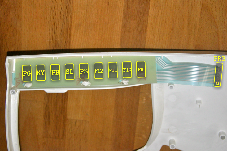
Note: The two keys PG(Program) and KY(Keypad) in the table above are not actually connected as shown. They serve special purposes and are not part of the normal key matrix when using the Kinesis controller. Instead, they are connected as follows:
| Pin | 1 | 2 |
|---|---|---|
| 3 | PG | KY |
KiCAD Layout
I used Stapelberg’s schematic to map the matrix to the Teensy2.0++ Controller that would be the new brain of the keyboard running QMK. Then I grabbed my calipers and started dimensioning the original logic board to ensure the mounting holes were correct as I had no way to verify if the mounting holes on the Stapelberg mod meant for the Kinesis Advantage matched the Kinesis Contoured 130. Then all was left to do was to port the design into KiCAD and let the auto-router work it’s magic (since this is small simple design I let the auto-router handle everything and just verified it’s work).
Sourcing the parts
A complete BOM is available here sans the PCB, which you can get the source/gerbers from my gitlab repository. Note some parts can be replaced with cheaper alternatives; such as getting pre-crimpled 10pin ribbon cables from china on eBay instead of getting the cable and terminating pieces and crimping it yourself.
Getting the parts was a little difficult for this as I could not get the original FFC connector that Kinesis used. The only (and I mean ONLY) other FFC connector that matched the pinout of the gold fingers was a Molex part on Digikey.
In addition the matching vertical connector was suitable for the two ribbon cables coming from the Function key rows.
When the parts arrived I test fit them to the gold fingers and for a while was scared they were too tight, until I discovered that the Molex parts have locking cuff that can be pulled out for inserting FFC cable into it and then depressed to lock the cable down. When pulled out both the gold fingers on the key wells and the FFC cable on the Function keys fit perfectly.
Note that if you want to do this project to a modern Kinesis Advantage2 you can actually use those vertical connectors in all locations where the board connects to key sections, I believe Kinesis simplified the layout to use these everywhere (even the thumb clusters). The PCB would have to be modified obviously.
Ensuring a Correct Fit
I’m always nervous when I design a PCB because once I send in the gerber files, thats it! Either I thought of everything and it would work or it would arrive only for me to realize I missed something, resulting in me either needing to hack it togther to get it to work or, worse, have to spin a whole new PCB.
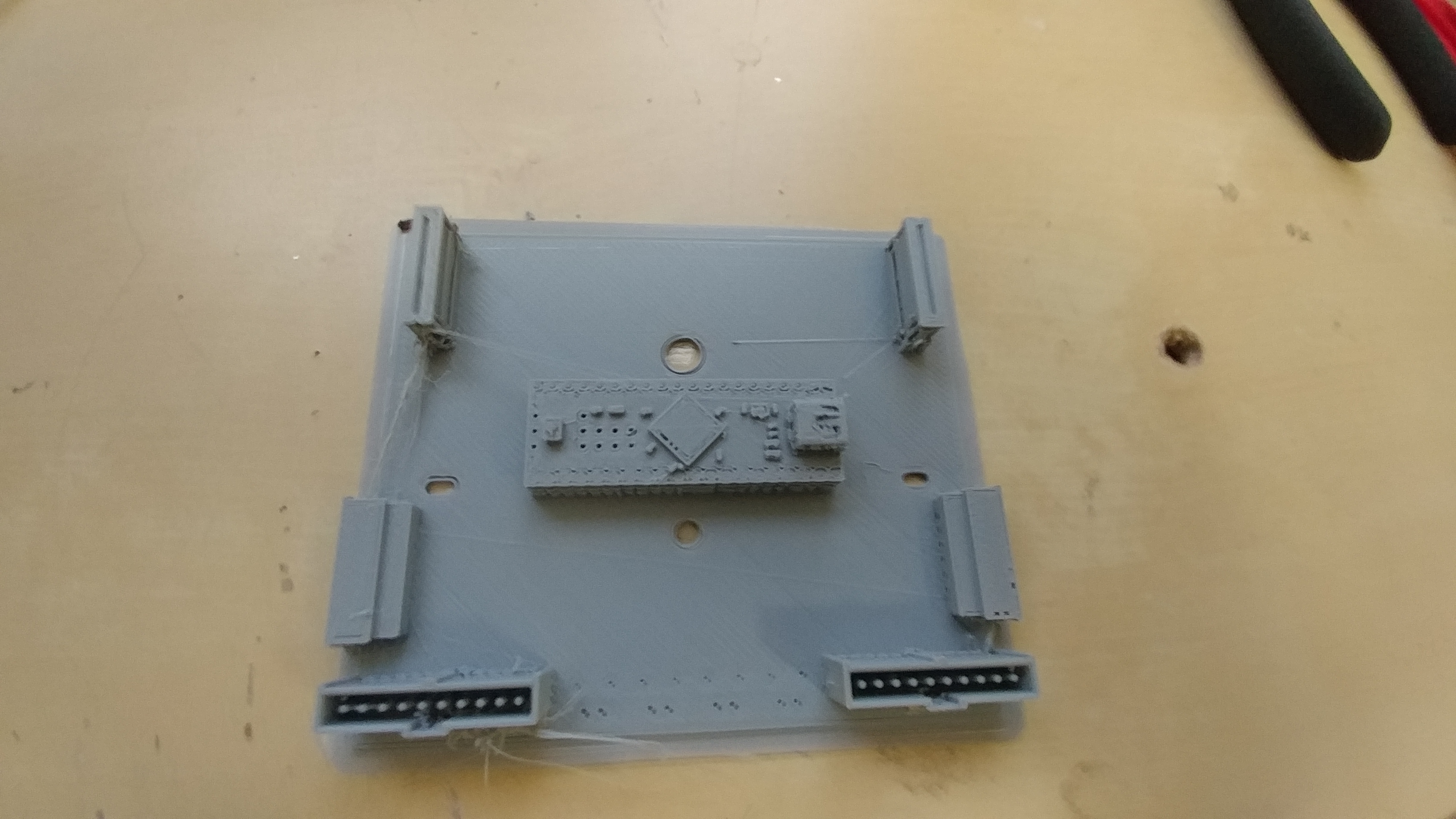
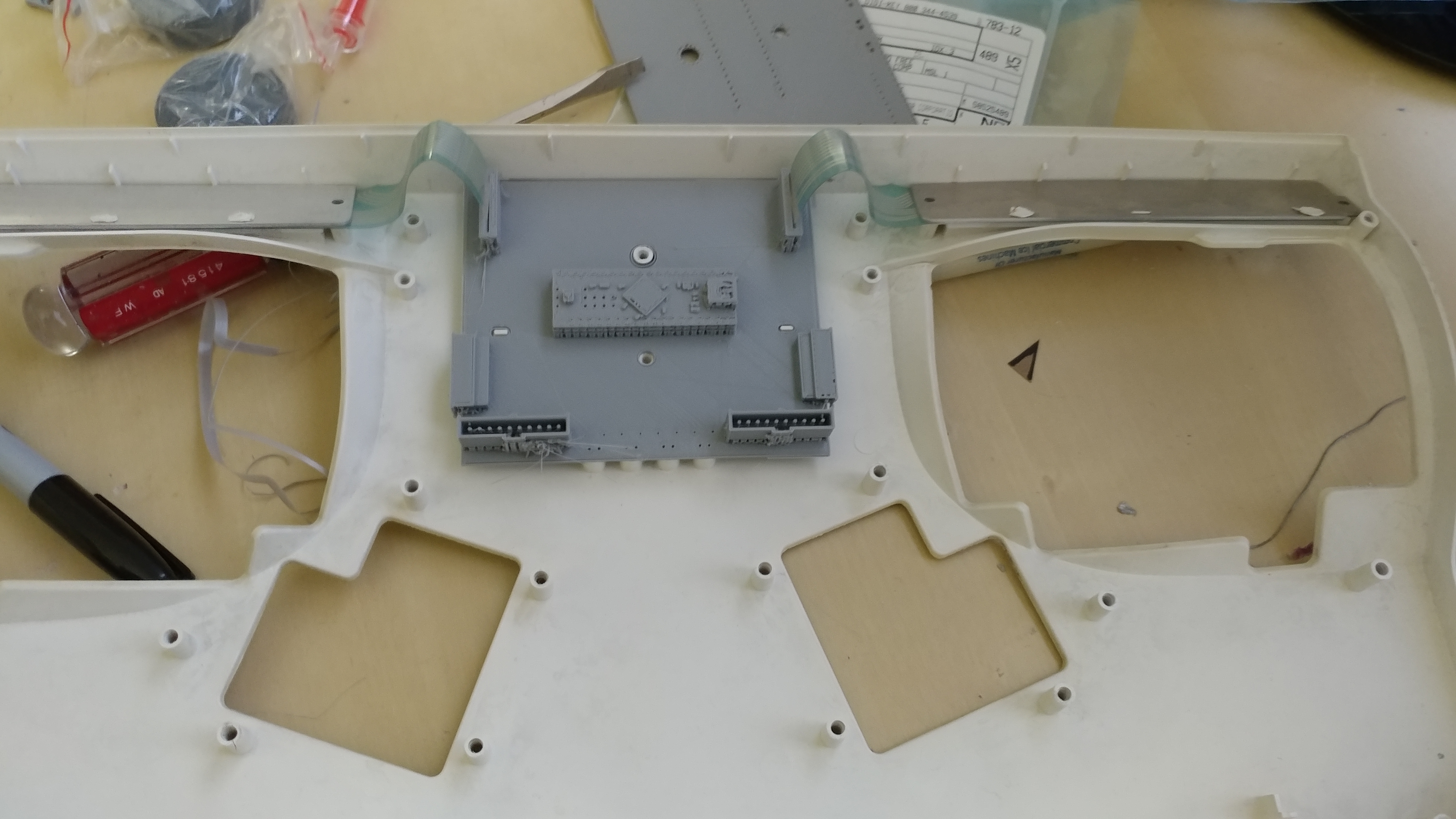
To ensure this wouldn’t be the case I designed the entire PCB and downloaded STEP files for all the parts, then I 3D printed the board with part models and also without part models.
The design with part models would be used to check clearances and correct mounting, whereas the one without would be used to ensure that the footprints I designed were all correct to the parts I ordered.
After checking tolerances I discovered that I could reduce the board size so the longest length would be just under 100mm, this was nice because it meant I could use a cheaper PCB service which often let you make a handful of copies of a board design under 100mmx100mm for only a few dollars.

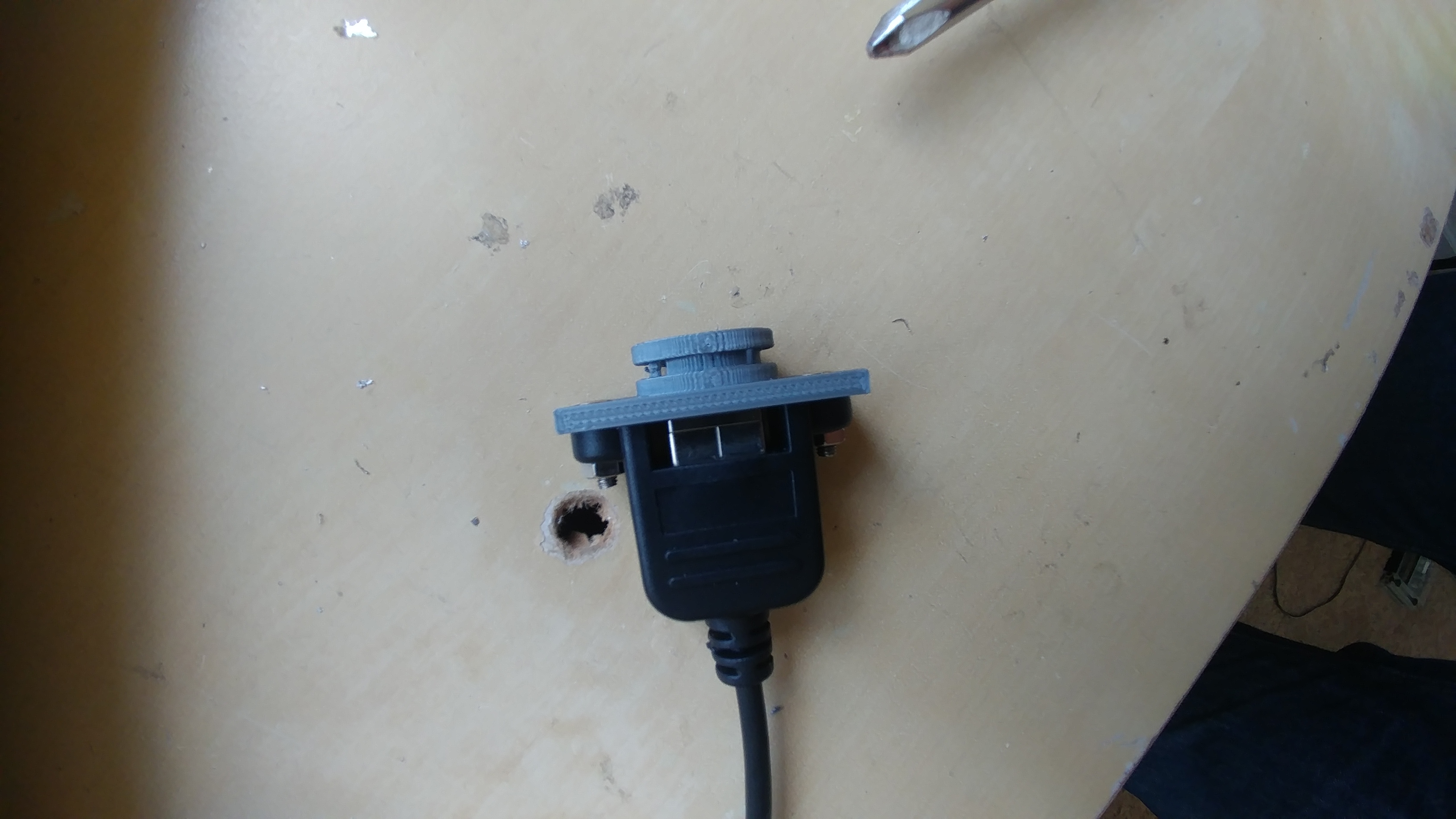
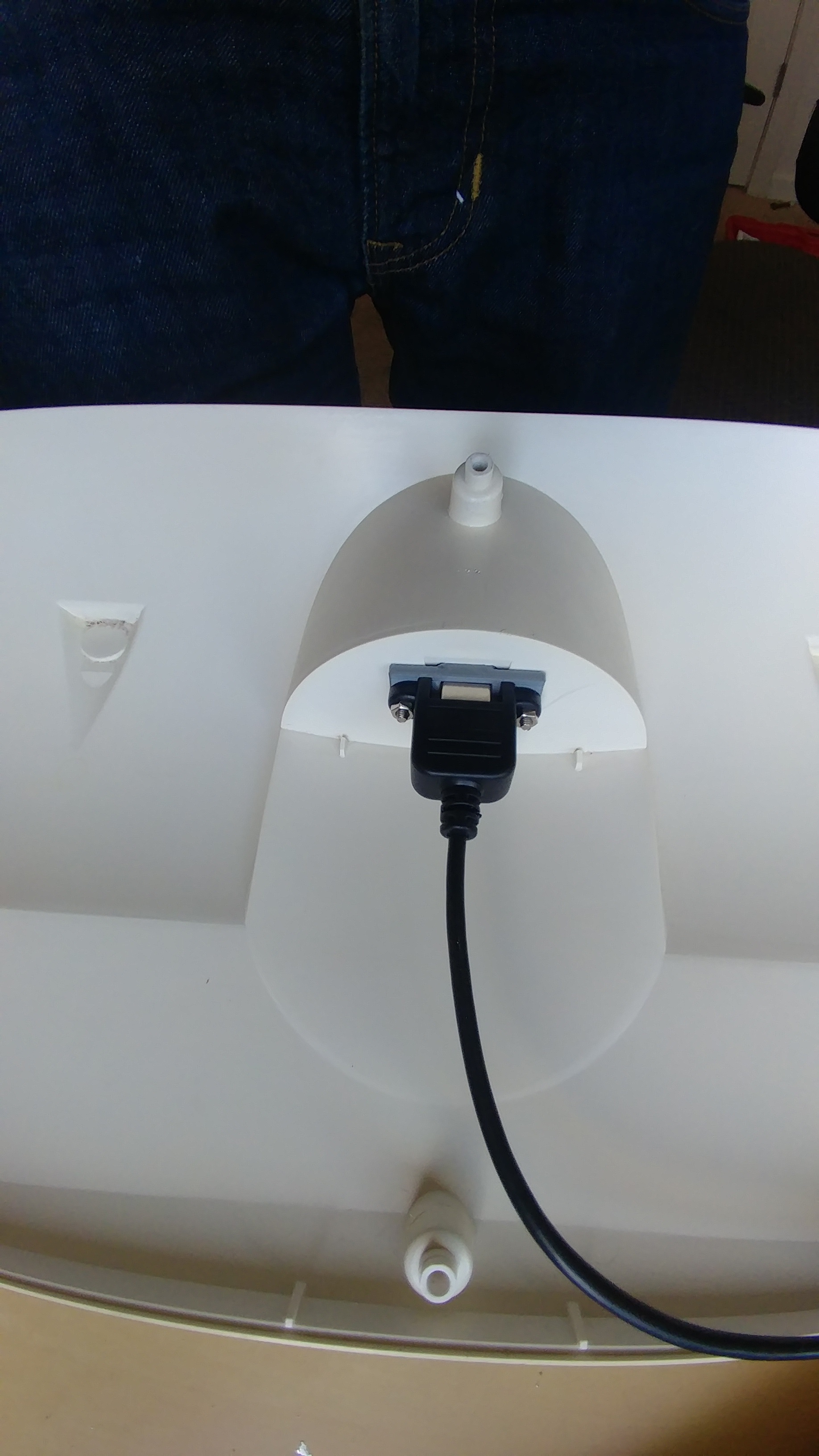
Routing the USB connector
Since the new board would be USB I needed a way to adapt the huge port that the old connector cable went through. I copied Humble Hacks idea to use a panel mounted USB-B Female port that connected to a mini USB-B Male, this way I could replace the external USB cable separatey if it ever broke.
My housemate helped me design a mount for the panel mounted connector that would take advantage of the C-Ring which secured the original connector to the chassis. This allowed me to not have to permanently modify the chassis by driling unsightly screw holes for the connector (which is what Humble Hacks resorted to). Then all I would need to do is use a USB-A Male to USB-B Male cable to plug into the keyboard.


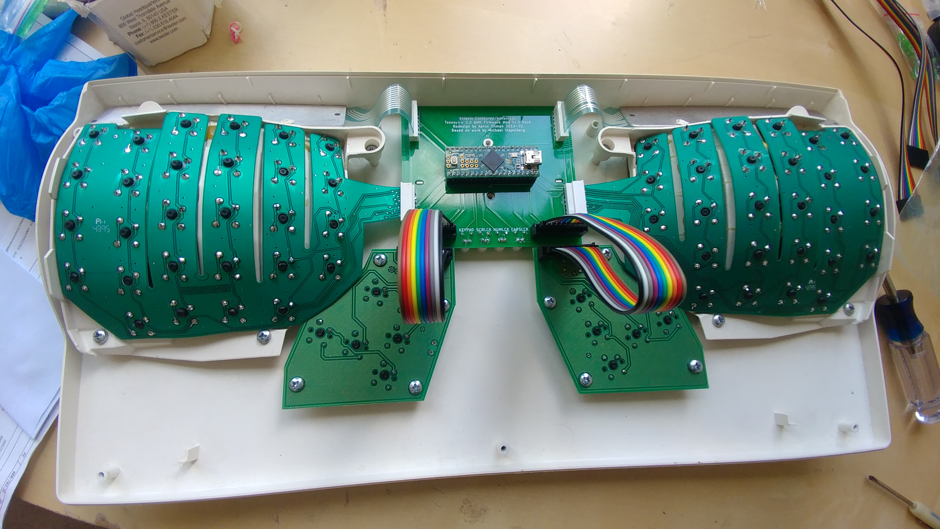
Puting it Together
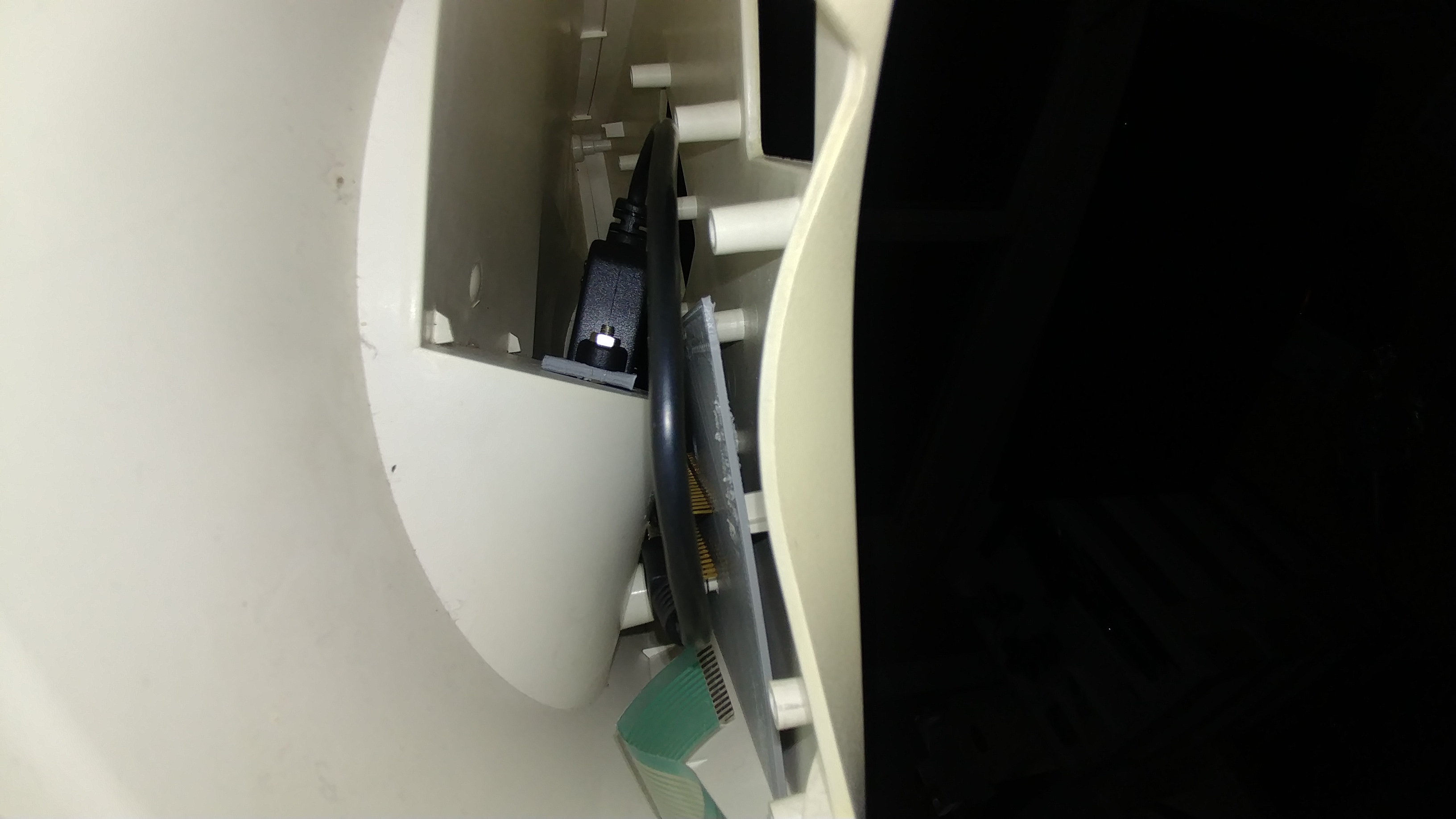
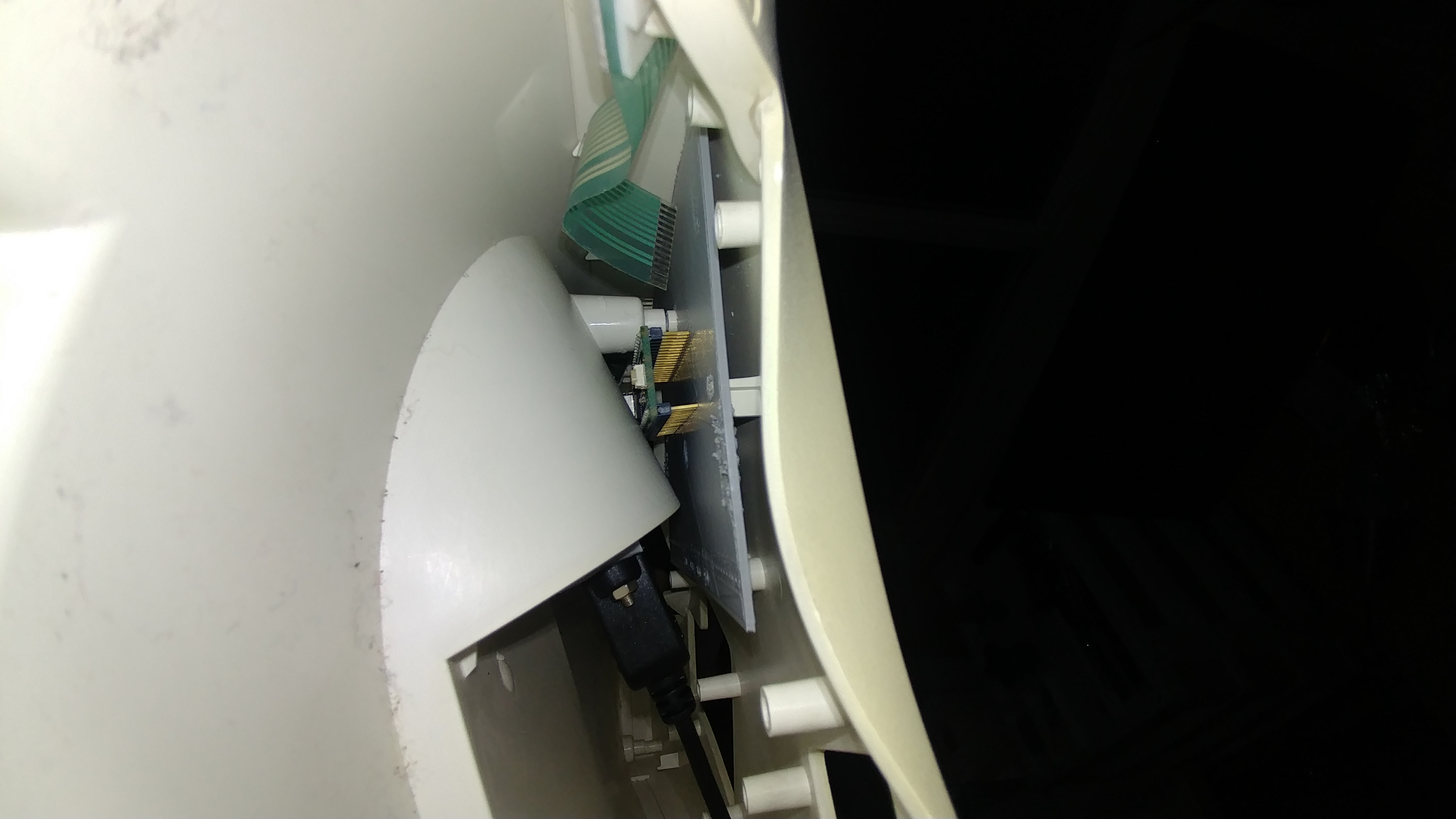
When the PCB arrived I soldered on my parts and breathed a sigh of relief when the board fit perfectly to the case mount. I connected up the key wells, the thumb clusters, and the Function key ribbon cable to the board and plugged the USB-B male end of the connector to the teensy and did a test fit. After I was happy with that I loaded QMK onto the Teensy, lucky for me QMK has decenlty wide support for the Kinesis and even a handful of keymaps. I used the default keymap to check it was working.
I screwed it together and viola! Had my new (old) keyboard up and running with QMK.
Future Plans
Now that I know my port of the Stapelberg Mod works I’d like to stake it a step further and take advantage of more of QMKs features, adding a speaker and LCD panel to the logic board and spinning out a new board.
I am also working on a custom keymap for QMK based on the keymap made by InsertSnideRemarks (now known as Tuesday John) which will be pretty similar but more suited to my needs as developer.
Update: 2020 November
I recently got around to performing this modification on my second Kinesis Contoured. This time I went with four different colored LEDs and have modified the QMK files to dis-associate the LEDs from the status of Caps Lock, Num Lock, Scroll Lock, and Keypad. Instead I now use the LEDs to indicate whether the following layers are active: Gaming Layer (Red), Advanced Layer (Orange), Function Layer (Green, also momentary only), MacOS Layer (Blue).
Since the LEDs are different colors their forward voltage drops are different and thus need different resistors. In addition I wanted their brightnesses to match which meant adjusting the current for each as some were extremely bright with less than 1mA (Red) and some needed as much as 16mA to reach the same brightness (Green). I suspect this is partially beacuse the LEDs are cheap and old.
To use my keymap that allows for custom LED control (instead of the “lock” keys controlling it), simply set up your QMK repository locally as instructed in QMK’s getting started guide. Then replace (or merge) the kinesis folder with the one I have uploaded to my repository. The only file it modifies is the kinesis.h by inluding my silman.h header; the rest of the files/folders are added and should be easy to merge together, not overwriting anything. I may make a PR for this to be added to the QMK repo in the future, but for now this is easy enough.
My keymap is available here, click to see all the features and layers in it: https://gitlab.com/Silman/kinesismod/-/blob/master/qmk_firmware/keyboards_/kinesis/keymaps/silman/